
 Continue with onX Maps
 Sign in with Facebook


Attn math-heads: help me think through this physics


|
Howdy interweb helpers-- any of you bored at work? Wanna help me think through the general forces involved in the following theoretical situation? Extension of a TR anchor point horizontally outward from the rock face (via some sort of extension device; don't worry about that part for now). Assume you are clipping into an existing two-bolt anchor and using either long runners or some other system to position the pulley-point for toproping horizontally out from (and likely slightly down from) the anchor bolts. 1. What sort of tension (pull-out) force would be transferred to the anchor bolts? How much multiplication of force are we talking here? 2. How much compressive force would the extension system have to withstand to position said TR pulley-point outward from the rock by, say, 12"? Assume these parameters: 1. 175 lb climber 2. tight belaying (i.e. essentially zero additional acceleration forces in a fall due to loose rope in the system; in fact, basically assume static weight resting on the rope the whole time) 3. max angle of the webbing from the bolts at, say, 50 degrees 4. therefore, the angle of the bend in the anchor slings at the pivot point at the end of the extension device would be 130 degrees (I suppose we could assume 60 degrees at the bolts, to make it a 30-60-90 triangle up top and keep the angle of bend at the pivot point at 120? I know 120 is a mathematically significant cutoff angle for force multiplication onto two anchor points [and yes, I know that practically speaking angles below 90 are really what we're going for with multipoint anchors; remember this is a theoretical exercise here], but in this case the force is going the other way on that wide angle-- inward rather than outward-- so the case is different here, right? This situation is a lot closer to a force pulling in a single direction that then gets bent slightly over an edge, right? Therefore, I really want to figure out how significant the outward force is at the anchor bolts; less worried about the compression force at the edge). 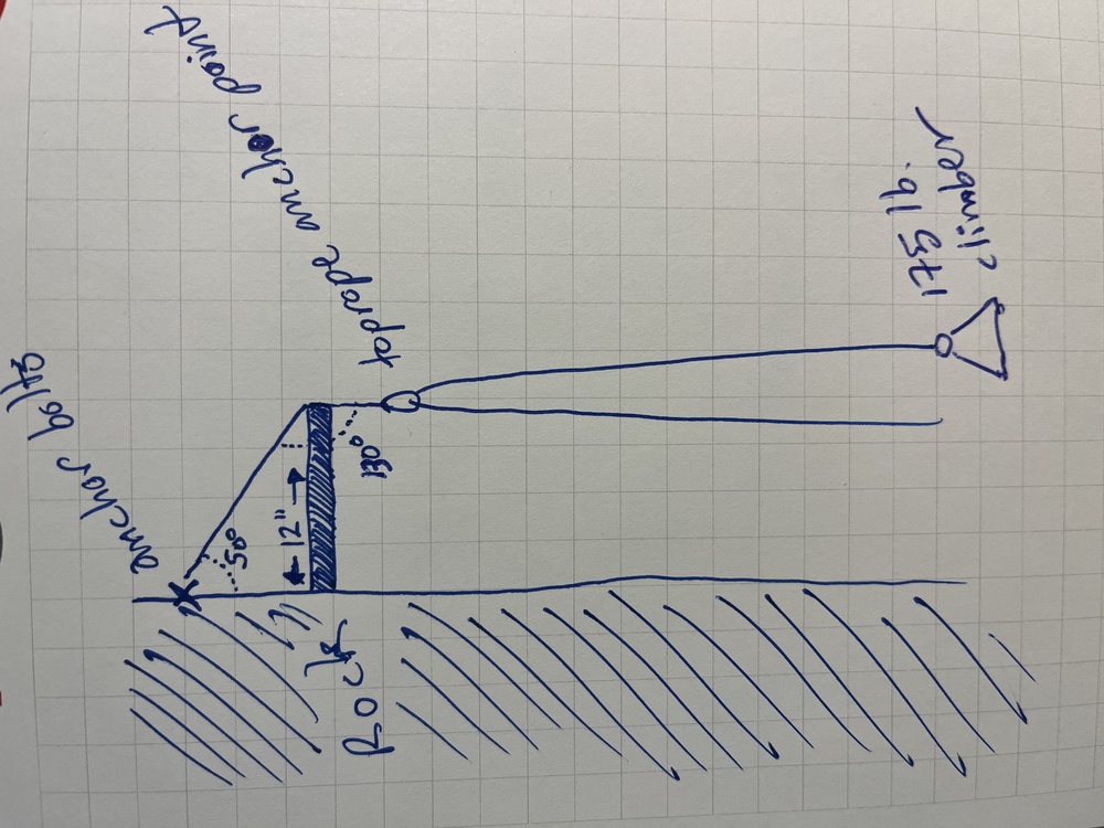 |
|
|
E = mc squared |
|
|
Why are you worried about pulling the bolts in tension at top rope loads? Are these rusty 1/4in buttonheads or something? Perhaps you should go watch some HowNot2 tests of pulling bolts in tension. They still hold 20+ kN even in some shitty rock. Also don't forget the torque that your 2x4 or whatever will be experiencing from the downward pull of the rope. It will not be purely in compression. I really have no idea how or why you are going to do this. |
|
|
Assuming no friction at the end of the extender and the load being applied straight down. The compression force on the extender and tension force on the bolts will be the same. To get this force you will need to do Sin(Angle @ rock) * The force on the TR anchor. Remember the Force on a TR anchor is theoretically 2* the climber's weight so in this situation you get. 175* 2 = 350 then 350 *sin(50) = 268 lbs. This will be the outward component of the force on the bolts and the compression force on your extender. The length of the extender doesn't matter other than in relationship to changing the angle at the rock. If this gives you what you need great if not I can dive in a little deeper into the friction forces that would come into play and the associated torque on the extender. Disclaimer I have done problem's very similar to this but do not do these computation on a regular basis so I might be missing something. Feel free to correct. |
|
|
175lb climber + 175lbs(ideal conditions with no efficiency loss) downward force to equalize the rope so overall load is 350lbs. Force perpendicular to the wall should equal 350lbs * sin50 degrees. so without accounting for mechanical efficiency, under ideal frictionless conditions, there would be 268.1136291lbs of pullout force |
|
|
Wait… i thought that said meth-heads. Nevermind… |
|
|
If you can set the angle of the compression member such that the angles of the rope above and below it are the same, it will be in pure compression with no bending force. The more acute the angle from the end of the "spreader" to the bolts, the harder the pull on the bolts. Anything tighter than 12 or 13 degrees starts to really multiply the force. |
|
|
The set up you're trying to make can easily be done with an A-frame / X-frame. |
|
|
Josh presents the diagonal member as a continuous sling that ends in the masterpoint hanging vertically - so it would carry 2x the climber's weight = 350 lb. If you assume that it's a perfect frictionless pulley at the tip of the extender, the diagonal portion of the sling would also carry 350 lb. 268 lb is the right answer for the outward force but you should also consider the shear, which would be 350*sin(50) = 225 lb. I modeled it as a truss which is a conservative solution to the problem, it gets rid of the frictionless surface at the tip of the extender - in that case you end up with much greater demands of 417 axial, 350 shear, and 544lb tension in the sling. I think this is closer to reality but without fully defining the fixities / boundary conditions, this is all I got. Edit: units mistake, 4200 lb*in 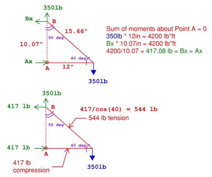 |
|
|
Jace has it right. Just think if that angle was 90 degrees instead of 50, the outward force would be infinite. For any angle over 45 degrees, the outward force will exceed the downward tension (350 lbs). Edit to add that a simpler way to the answer is this. W= downward pull, F= outward pull, and T= tension in the diagonal piece. Then T cos(theta) = W T sin(theta) = F So, F = W tan(theta). Here W = 350 lb, theta =50 degrees. |
|
|
Josh does state bolts for the anchor, and using either long runners or some other system to position the pulley-point .... so assuming a 2 leg bridal / attachment, that load (544lb) should be distributed to those 2 pieces. |
|
|
Good call, he does specify two bolts, I was caught up only thinking in 2-D. I haven't sat down to do that second step of the calc but that sounds right. Totally dependent on that bridle angle and if the system is symmetric or not. I'm thinking the axial force in each would be half what i calculated above, but now we are introducing shear in another axis. I'm not sure at what point that becomes problematic, I could make a model in the Hilti software... |
|
|
Whenever i am really mathmatically confabulated i just remember that the integral of e to the x is a function of u to the n. that's really all you need to know in life. that being said, it seems like people are assuming there isn't a spread between the bolts themselves. may want to take that into account also, may even need a couple more greek letters, although if they are close together it is probably majoring in the minors. |
|
|
This is awesome work, y'all. Thanks for the help conceptualizing the forces involved in the situation. Much appreciated. And Slim is not wrong-- good baseline to remember throughout life ;). |
|
|
Fun problem and one where Jace's truss analysis is very informative! I bet (if you weren't careful) you would see the horizontal leg of the extender frame buckle before the bolts or diagonal slings break. I forget the buckling formula... hmm.. what material and shape would be best I wonder? |
|
|
Josh wrote: Just to add to this, a good conceptual framework for loads from rope is that they can only provide tension. Without the rope being fixed to some point, the most load the rope can see is the weight of both climbers. (Assuming no friction, ideal gases, cows as spheres). So in your situation, no matter how many times you redirect your rope with pulleys and contraptions, the most load your anchor should see is the mass of the climbers. This is the same deal for hauling, where for some reason people think that you can create huge loads (barring stuck bags or whatever) |
|
|
All these calculations are static loads, no moving, bouncing, or rope slack. All this can bring the load up to 4Kn (880lbs) |
|
|
Pi....I like Pi....:P |
|
|
Rick.Krause Krause wrote: Taking into consideration dynamics is fine, but trying to calculate for it is not usually functional when you can justy apply a safety factor, which is rigging 101. |


