
 Continue with onX Maps
 Continue with Facebook


CAD model of a BD camalot number 1


|
|
John O from Jersey wrote:OK Kyle, let's get this thread back to something useful - the coffee mug that we now all want!!!!! Mock up looks great but the handle should come off one of the angles so when you hold it, you'll drink from a flat. Love the carabiner handle idea. This needs a kickstarter campaign!!!! I'm in for 25. Don't forget to drill the holes for the sling :-) John OI would greatly prefer an oval or a stiff cord for a handle. The cam lobe seems out of place. 25? Geez, I'm down for 2. |
|
|
 Given a shape (logarithmic spiral) and a set scalar multiplier (this sets the size), you end up with a plot: 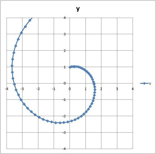 The plot is actually generated using radial coordinates and translated to Cartesian. But ANYWAY... You can now find the min and max of a lobe range between 0 and pi/2 (90 degrees). For this particular case, the lobe's minimum length is 1". Assuming a common axis, it's minimum size would be 2". You can determine your new range given: 2*Range_min-Axle Separation 2*Range_max-Axle Separation Then you can produce the following table:  You can see that the range ("delta") actually remains unchanged despite axle separation. So what good does it do? The secret is the cam lobe size. For instance, the larger the cam lobe, the greater the range. So rather than having a changing cam angle, offsetting the axles lets you use a LARGER lobe which has a LARGER inherent range:  So you can see that having two cams with the same smallest size can change drastically by using a larger lobe and offsetting the axles. |
|
|
Charlie S wrote: Given a shape (logarithmic spiral) and a set scalar multiplier (this sets the size), you end up with a plot: The plot is actually generated using radial coordinates and translated to Cartesian. But ANYWAY... You can now find the min and max of a lobe range between 0 and pi/2 (90 degrees). For this particular case, the lobe's minimum length is 1". Assuming a common axis, it's minimum size would be 2". You can determine your new range given: 2*Range_min-Axle Separation 2*Range_max-Axle Separation Then you can produce the following table: You can see that the range ("delta") actually remains unchanged despite axle separation. So what good does it do? The secret is the cam lobe size. For instance, the larger the cam lobe, the greater the range. So rather than having a changing cam angle, offsetting the axles lets you use a LARGER lobe which has a LARGER inherent range: So you can see that having two cams with the same smallest size can change drastically by using a larger lobe and offsetting the axles.your calculations on cam range are all wrong though. |
|
|
Tom Mulholland please post some pics of what you print and the pull test results. I am very curious to know where the fail point in the cam lobes are(possibly different from actual aluminum fail point though). I am considering printing the lobes on my 3D printer, but I have no way to do a pull test or anything useful with them afterwards. |
|
|
Kyle Cobbler wrote:Tom Mulholland please post some pics of what you print and the pull test results. I am very curious to know where the fail point in the cam lobes are(possibly different from actual aluminum fail point though). I am considering printing the lobes on my 3D printer, but I have no way to do a pull test or anything useful with them afterwards. nice legs, I think john o was talking about $25 not 25 mugs, if you guys are serious I could make a few. Kinda agree with the cam lobes look out of place though.I'll take 2 mugs with locking biners to hang off my pack. These can double as a bear bell |
|
|
 I have one of these, bought it off ebay for a couple bucks, but it's small, like maybe 6oz, and the biner is cheap and flimsy. If you made a Hex one that was like 12oz with a nice biner, I would be in. |


|
Kyle Cobbler wrote:As luck may have it I am also pretty good at making coffee mugs in particular the extruded kind. Wouldn't be the hardest thing ever to make a couple of extrusion dies for the hex and a cam lobe handle, not so sure I can do and anodized glaze though.... a few of my extruder mugs are here mixed in with wheel thrown stuff(twards the end of pics I think the ones with the spiral handles. coroflot.com/Schumakk/Ceram… sooooo like this:Sweet mock up Kyle! When I mentioned the cam lobe I had a slightly different look in mind. I was thinking the lobe could be most ergonomically when flipped upside down from the way you have it. Also rotated 180 degrees along the longitudinal so that the curve works in the favor of the user. Basically the "spiral" side would be connected at a single point on the mug. It way look weird though. If we do this Kickstarter thing I think a variety of options should be given. #11 with #4 lobe and #8 with #3 lobe for the kids! Haha. Also, the "vintage carbiner" design is quite awesome too! If I get any time at the end of this week I will start forming up a Kickstarter campaign and will PM anyone in this thread that has shown interest in throwing this thing together. Maybe we can all benefit from the idea and sell these like this: Mt. Hood HipsterWare Cheers, Mac |
|
|
i think the cam lobes wouldn't be ergonomic and would be somewhat out of place (in most places and with most people cams have replaced hexes). i think, if possible, a chouinard oval would be a better fit. |
|
|
eli poss wrote:i think the cam lobes wouldn't be ergonomic and would be somewhat out of place (in most places and with most people cams have replaced hexes). i think, if possible, a chouinard oval would be a better fit. and yes, if this is made i will certainly buy one.For sure.The people have spoken. Regular old 'biners would be easy enough. I have 3 Chouinard ovals...but that's it. Older Chouinard ovals are difficult to pick up, maybe we can have the option where the person can ship us their own carabiner to attach on there. Are we thinking a full carabiner attached, or a carabiner split in half and two points connecting onto the mug? Personally I think half of one carabiner is a perfect size, but I also have smaller hands than most. Cheers, Mac |
|
|
i was actually talking about it being completely ceramic and the handle being designed to look like an chouinard oval. i would imagine it would be quite difficult to attach a real biner to a ceramic mug. i would also go for a real biner, though |
|
|
eli poss wrote:i was actually talking about it being completely ceramic and the handle being designed to look like an chouinard oval. i would imagine it would be quite difficult to attach a real biner to a ceramic mug. i would also go for a real biner, thoughI definitely missed that post. I didn't know that you were referring to a ceramic mold. In which case, a lot of different options can be done.. I don't know if a metal carabiner would be able to stay on the ceramic though either. |
|
|
Can we see some cool spaceship renders now? |
|
|
I worked hard on this, you best appreciate it. |
|
|
[Captain Picard facepalm here]  |
|
|
Kyle Cobbler wrote:I worked hard on this, you best appreciate it.that doesn't look very aerodynamic. you may need to add some red bull to the mix |
|
|
well what is it guys? meer cats or red bulls? maybe we can get some red bulls to eat meer cats and the methane produced can provide rocket fuel, I know, i'm a genius thank me later when we get to mars :) |
|
|
Thoughts? |
|
|
A hydraulic piston? Hydraulically that wouldn't work. |
|
|
is that something that would keep a small load on to prevent it from walking? if so, thats a great idea. if not, how about a spring where you can adjust the tension (put it on low to place and then put it on high to reduce walking)? |
|
|
Do y'all really have that much trouble with walking cams to warrant such measures? Try slinging it! Sounds like a solution looking for a problem to me. |


